Gerber and drill



Example
The example set is the ST Nucleo-L031K6 board, revision MB1180 C, a four-layer board. The example BOM and the example centroid describe the same board, so the three files fit together the way yours should.
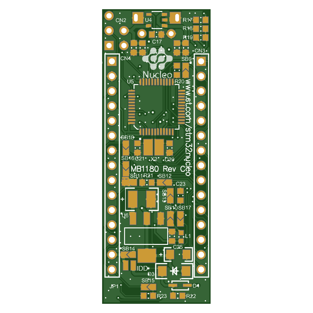
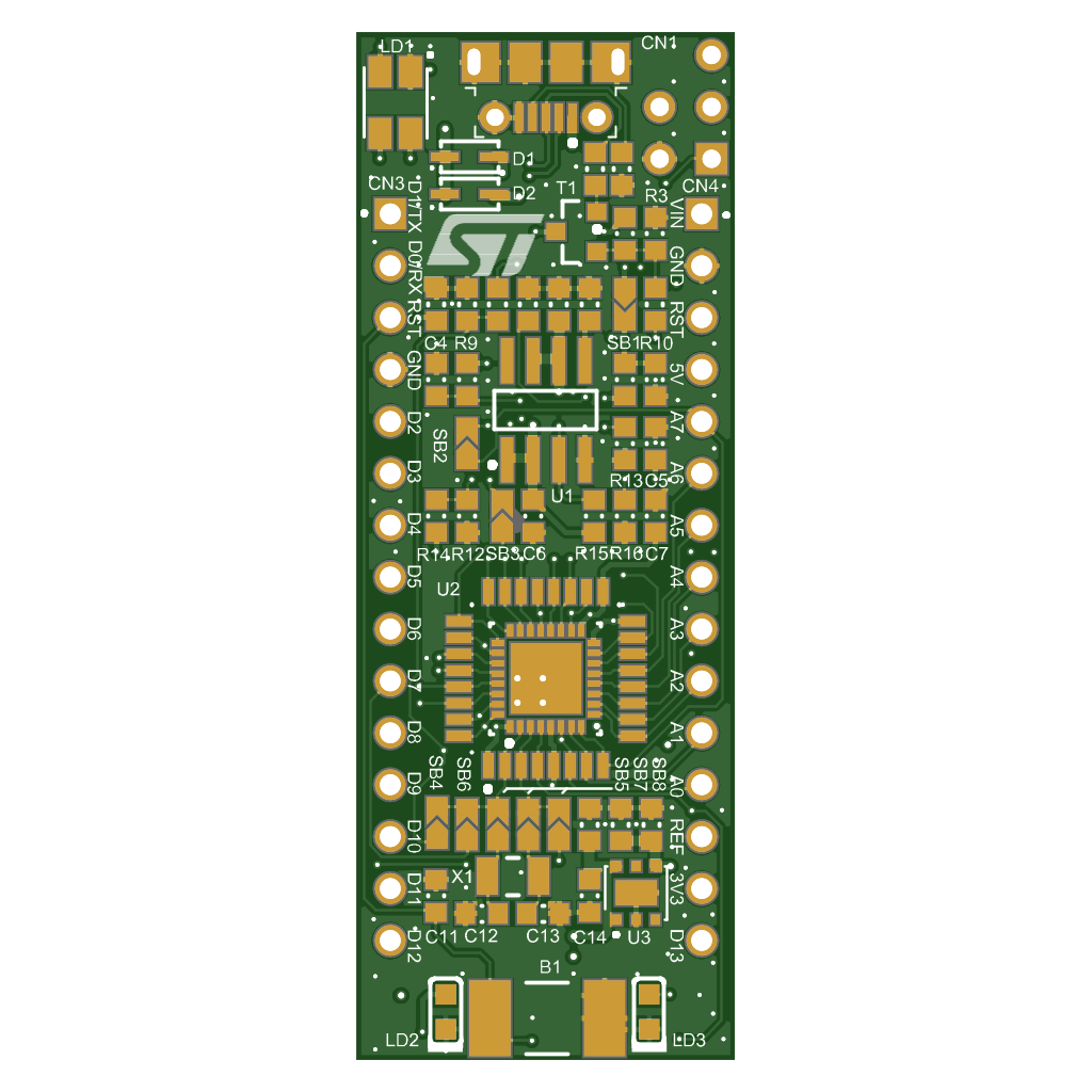
Do not forget the drill files
This is the file people forget most often. In most CAD tools the drill data is a separate export next to the Gerber layers. In KiCad, File → Fabrication Outputs → Gerbers plots the layers, and the drill files come from the Generate Drill Files button in the same dialog. In Altium, Gerber Files and NC Drill Files are two different fabrication outputs, and in an Output Job they are two separate entries. A set without drill files has no holes. Our upload check tells you when they are missing. They usually end in .drl, .xln, .txt or, as in the example, .exc.
The outline
Send the board outline as a file of its own, not drawn on a copper or silkscreen layer. One closed contour on an otherwise empty layer, drawn with a thin line, with every internal cutout as a closed contour of its own. The centre of that line is where the board is cut. Keep dimensions, notes and mounting drawings off this layer; they belong in a separate mechanical drawing. Name the file so its purpose is clear. We recognise the usual names: Altium's .gko or .gm1, KiCad's Edge_Cuts.gbr, Eagle's .gml, or simply a Gerber file called outline, as in the example set with its board outline.gbr. Better still, let your CAD tool write Gerber X2, which tags the file as the profile so no name is needed.
Look before you send
Our open source Gerber viewer renders a Gerber and drill set in your browser.